4. 3D Visualization Controls#
4.1. Camera Controls#
The following mouse actions and keyboard shortcuts control the camera in the 3D viewport:
Image |
Action |
Description |
|---|---|---|

|
Rotate |
Click and hold the left mouse button to rotate the model |
|
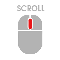
Scroll |
Use the mouse wheel to zoom in or out |
|
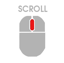
Pan |
Press and hold the mouse wheel while moving the model |

|
Change Center of Rotation |
Hold Ctrl and click a point on the model to set it as the new centre of rotation |
|
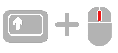
Zoom on a Specific Part |
Hold Shift and click and drag with the mouse wheel button to draw a zoom rectangle on the model |

|
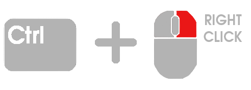
Select |
Right-click on an element or node to select it |
|
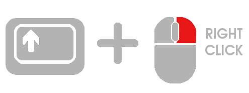
Multi-selection |
Hold Shift and right-click. A green rectangle will appear as you move the mouse; all elements within the rectangle will be selected |
|
Deselect Individual Item |
Hold Ctrl and right-click on an item to deselect it |

|
Autofit |
Press F to autofit the model in the viewport |

|
Toggle Axis 2D |
Press A to toggle vertical and horizontal reference guides in the 3D window |

|
Toggle Bounding Box |
Press B to toggle the model bounding box |

|
Toggle Camera Info |
Press C to display camera parameters in the viewport |

|
Clear Selection |
Press Esc to clear the current selection |

|
Toggle Free Edges |
Press E to toggle free edges visibility |

|
Show All Elements |
Press I to show all elements |
All these mouse controls and keyboard shortcuts can be customized to suit your preferences. For more information on how to modify them, see Sections 2.1.5.2 Keyboard Shortcuts and 2.1.5.3 Mouse Controls
4.2. Visualization Toolbar#
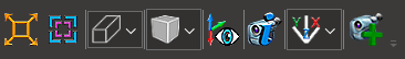
The Visualization Toolbar provides controls for the view projection, mesh display, coordinate axes, and predefined viewpoints.
4.2.1. Autofit#
 Clicking Autofit centers the model in the window.
4.2.2. Center Element/Plane#
 Clicking Center Element/Plane centers and orients the camera based on the active selection.
Activation conditions:
Elements: exactly one 2D element selected
Nodes: exactly three nodes selected
Behavior:
1 2D element: the camera centres on the element’s centroid and orients perpendicular to the face normal, looking outward
3 nodes: the camera centres on the triangle’s centroid, orients perpendicular to the plane defined by the three nodes, and adjusts the distance accordingly
4.2.3. Projection Mode#
You can choose between two different view types:
 Orthogonal View
 Conical View
4.2.4. Mesh Mode#
The mesh can be displayed in five rendering modes:
 Opaque: The default setting.
 Opaque Wireframe
 Transparent
 Transparent Wireframe
 Opaque Feature Edges
4.2.5. Get Free Edges#
 This function identifies and displays the free edges of the model, highlighting areas where there are no adjacent elements.
4.2.6. Show/Hide Axis#

Clicking the icon hides the coordinate axes; the icon changes to show a crossed-out eye. Click again to restore the axes.
4.2.7. Show Camera Info#
 Clicking Show Camera Info displays the camera parameters in the viewport. You can move the Camera Info box to any location within the window.
4.2.8. Predefined View#
Select a predefined viewpoint to orient the camera along one of the principal planes of the coordinate system:
 X, Y
X, Y X, Z
X, Z Y, X
Y, X Y, Z
Y, Z Z, X
Z, X Z, Y
Z, Y X, Y, Z
Orientation Cube#
In addition to the toolbar buttons, an Orientation Cube is displayed in the lower-left corner of the viewport, next to the global coordinate system. This cube provides a quick and intuitive way to orient the model by clicking directly on its faces, edges, or vertices:
Clicking a face orients the model to the corresponding standard view (front, back, top, bottom, left, right).
Clicking an edge orients the model to a view aligned with the two adjacent faces.
Clicking a vertex orients the model to an isometric view from that corner.
Two visual styles are available for the cube:
Flat cube — the default style.
Rubik cube — an alternative style matching the NaxToView corporate design.
The cube style can be changed in Tools → Options.
4.2.9. Save View#
 This option saves the current camera configuration as a new view in the Session Tree. The new view appears alongside existing views and can be restored at any time.
For details, see 7. Session Tree.