2. Interface Overview#
The NaxToView interface is divided into several functional zones. Understanding these zones will help you navigate efficiently.
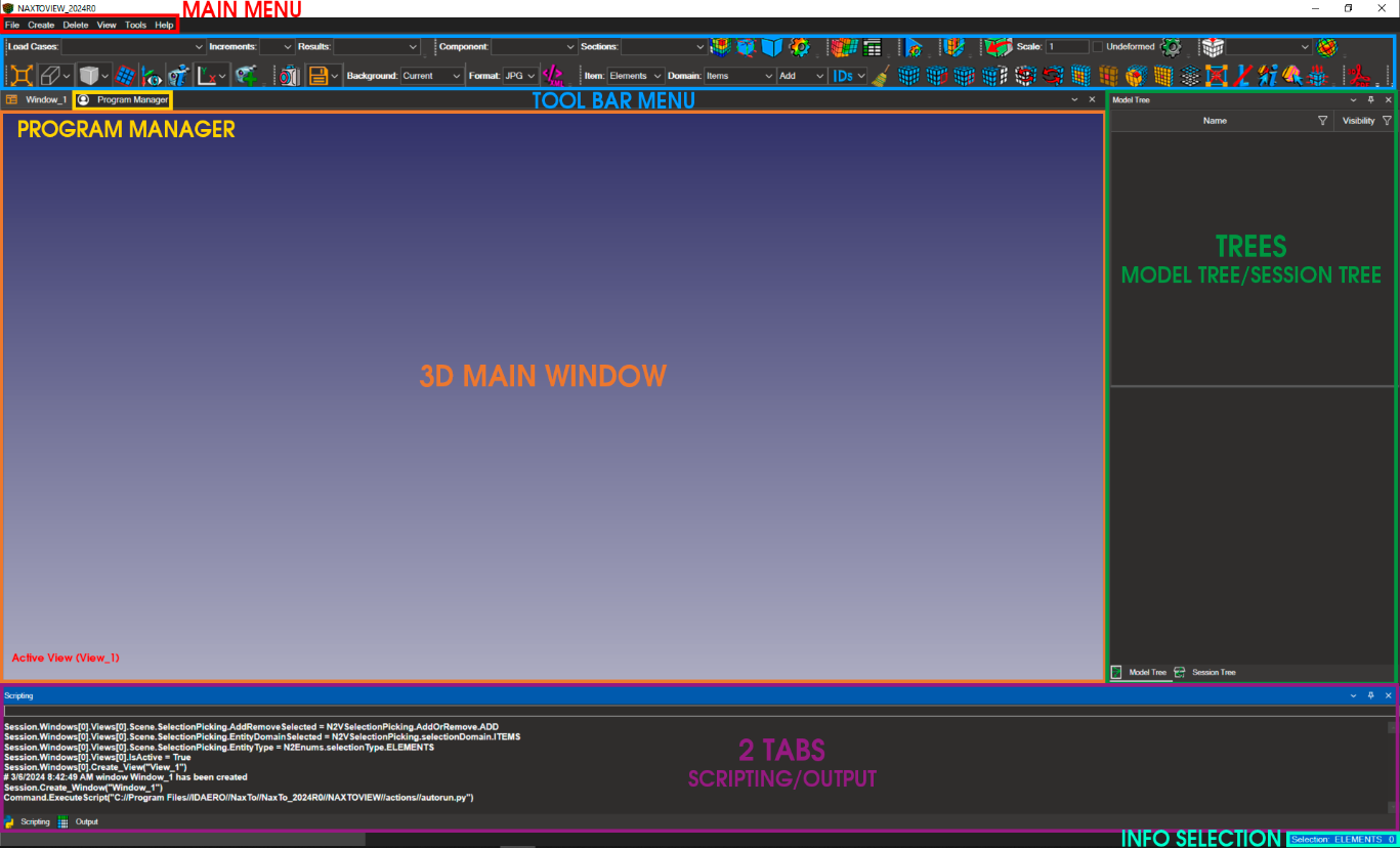
All windows in NaxToView are floating and dockable, allowing you to customize their arrangement. You can reset to the original layout at any time.
The sections below detail each area of the interface.
2.1. Main Menu#

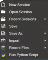
2.1.1. File#
New Session: Creates a new session.
Open Session: Opens a previously saved session.
Recent Session: Displays the most recent sessions you have worked with.
Save: Saves the current session in
.n2vformat (an XML-based format).Save As: Saves the session in
.n2vformat with a name and location of your choice.Import: Several options:
“Import Model and Results”: Loads mesh and results from output files:
*.op2,*.xdb,*.hdf5,*.h3d,*.odb,*.rst.“Import Model”: Loads only the model mesh. Supported input formats:
*.bdf.“Import Results”: Loads only results from output files:
*.op2,*.xdb,*.hdf5,*.h3d,*.odb,*.rst.“Import Geometry”: To load geometry from
.stlfiles.
Export: The Export menu is enabled only after importing a Nastran or OptiStruct input file. Once enabled, this menu allows you to export the entire model with customizable format options.
Recent Files: Shows the last files you have worked with.
Run Python Script: Executes a Python script file.
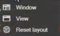
2.1.2. Create#
Window: Creates a new window.
View: Creates a new view inside the selected window.
Reset Layout: Resets NaxToView to the initial GUI layout.
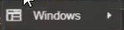
2.1.3. Delete#
Window: Removes the selected window.
Note
To delete a view inside a window, right-click the view in the Session Tree.
2.1.4. View#
Use this menu to select which GUI windows appear on screen. Items with a check mark are visible.
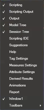
This menu also controls which toolbars are visible.
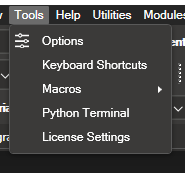
2.1.5. Tools#
This menu provides access to NaxToView Options, Keyboard Shortcuts, Macros, Python Terminal, and License Settings.
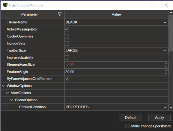
2.1.5.1. Options#
Opens a dialog for customizing options including theme colours, icon size, logo visibility, background colours, labels, selection, and more.
2.1.5.2. Keyboard Shortcuts#
The Keyboard Shortcuts dialog lets you view and reassign shortcuts for accessing NaxToView features.
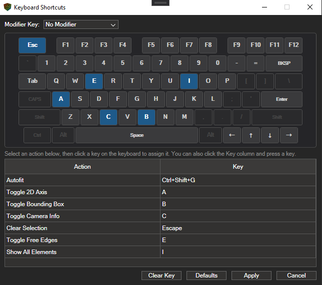
The default shortcuts are:
Image |
Action |
Description |
|---|---|---|

|
Autofit |
Press F to autofit the model in the viewport |

|
Axis 2D |
Press A to toggle vertical and horizontal reference guides in the 3D window |

|
Bounding Box |
Press B to toggle the model bounding box |

|
Camera Info |
Press C to display camera parameters in the viewport |

|
Clear Selection |
Press Esc to clear the current selection |

|
Free Edges |
Press E to toggle free edges visibility |

|
Show All Elements |
Press I to show all elements |
2.1.5.3. Mouse Controls#
The Mouse Controls dialog lets you view and reassign controls for accessing NaxToView features.
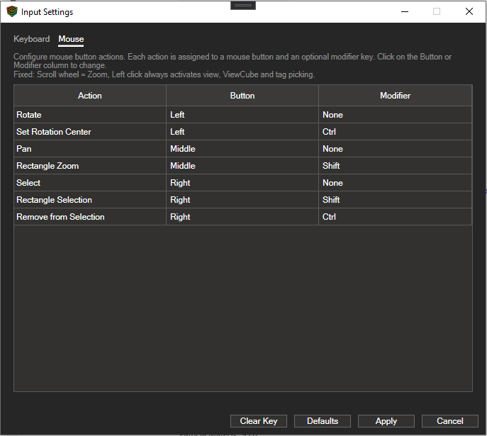
The default mouse controls are:
Image |
Action |
Description |
|---|---|---|

|
Rotate |
Click and hold the left mouse button to rotate the model |

|
Scroll |
Use the mouse wheel to zoom in or out |

|
Pan |
Press and hold the mouse wheel while moving the model |

|
Change Center of Rotation |
Hold Ctrl and click a point on the model to set it as the new centre of rotation |

|
Zoom on a Specific Part |
Hold Shift and click and drag with the mouse wheel button to draw a zoom rectangle on the model |

|
Select |
Right-click on an element or node to select it |

|
Multi-selection |
Hold Shift and right-click. A green rectangle will appear as you move the mouse; all elements within the rectangle will be selected |

|
Deselect Individual Item |
Hold Ctrl and right-click on an item to deselect it |
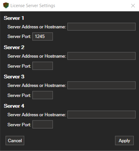
2.1.5.6. License Settings#
The License Settings dialog connects the NaxTo suite to the license server. Up to four license servers can be configured; each acts as a failover for the others.
Server Address or Hostname: The IP address or hostname of the server.
Server Port: The port on which the license service is running.
2.1.6. Help#
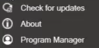
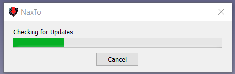
Check for Updates: Checks for available updates.
About: Displays the current NaxToView version.
2.1.7. Utilities#
The Utilities menu provides access to auxiliary tools for specific data handling and format conversion operations.
Currently, this section includes a conversion utility that imports HWASCII result files and converts them to the NaxToHDF5 format used internally by the NaxTo ecosystem. This enables result data stored in .hwascii files to be fully integrated into the standard NaxToView post-processing pipeline.
HWASCII → NaxToHDF5 Converter: Opens a utility that reads a
.hwasciifile containing simulation results and converts it to NaxToHDF5 format. The converted files can then be loaded and handled in NaxToView in the same way as any other supported results format.
2.1.8. Modules#
The Modules tab provides access to advanced functionalities based on NaxToPy. It currently includes the following tools:
N2PNeuber: Opens a dedicated interface for calculating and importing results using the Neuber method, facilitating nonlinear analysis from elastic results.
N2PUpdateFastener: Opens an interface for updating fastener-type elements, allowing their properties to be modified and managed efficiently within the model.
These tools provide additional post-processing and advanced editing capabilities directly from the NaxToView interface.
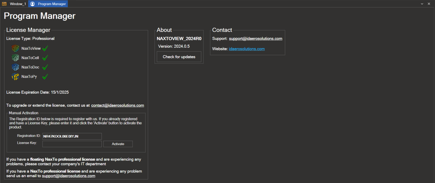
2.2. Program Manager#
This window displays information related to licenses, contact details, version numbers, and similar administrative data.
2.3. Model, Session and Includes Tree#
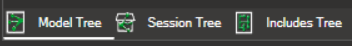
2.3.1. Model Tree#
This tree organises the finite element model by key attributes. Select individual items and use right-click actions to select elements of that type, hide them, or isolate them in the 3D view.
The attributes are:
Entities
Properties
Materials
Parts
Types of elements
Connectors
Geometry
Sets
Groups
Coordinate Systems
For details, see 6. Model Tree.
2.3.2. Session Tree#
This tree manages the 3D windows and views within the application. Navigate the tree to access specific windows and views; right-click actions are available for operations on windows and views.
For details, see 7. Session Tree.
2.3.3. Includes Tree#
This tree manages the file structure within input files compatible with Nastran, Abaqus, and OptiStruct. Navigate the tree to display, hide, isolate, or select specific file elements. For details, see 8. Includes Tree.
2.4. Toolbar#
2.4.1. Results#
The Results toolbar provides tools for displaying results.

For details, see 9. Results Visualization.
2.4.2. Plot Contour#
The Plot Contour toolbar provides tools for model plotting.

For details, see 9.1. Contour Plot.
2.4.3. Reports#

The Reports toolbar provides tools for configuring reports.
For details, see 13. Reports.
2.4.4. Animations#

The Animations toolbar controls result animations.
For details, see 14. Animations.
2.4.5. Free Bodies#

The Free Bodies tool enables you to make cuts or sections in a model’s structure to analyze the forces transmitted through that section.
For details, see 15. Free Bodies.
2.4.6. Deformed Settings#
The Deformed Settings toolbar provides tools for visualizing deformation under applied loads.
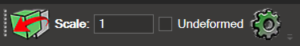
For details, see 9.6. Deformed Settings.
2.4.7. Expand 1D Elements#
 This button is available in the toolbar when a model containing 1D elements is loaded. It increases the visual thickness of 1D elements, making them easier to select and inspect.
The scale factor can be configured in Options under the Zoom 1D Size parameter.
2.4.8. Attributes#
The Attribute Settings toolbar provides tools for creating and managing attributes.

For details, see 16. Attributes.
2.4.9. Camera Mode#
The Camera Mode toolbar controls 3D model visualization.
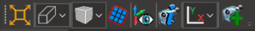
For details, see 4.2. Visualization Toolbar.
2.4.10. Saving an Image#
The Image Options toolbar provides tools for capturing images of the finite element model displayed in the 3D window.
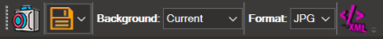
For details, see 11. Saving an Image.
2.4.11. Selection Tools#
The Selection Tools toolbar provides tools for selecting elements within the model.

For details, see 5. Selection Tools.
2.4.12. Interactive PDF Files#

Exports the currently loaded model and results from the 3D window as a 3D PDF file.
For details, see 23. Interactive PDF Files.
2.4.13. Load coordinate systems from a CSV#

Loads coordinate system definitions from a CSV file for use with entity-specific (node/element) results.
For details, see 9. Results Visualization.
2.4.14. Tags#
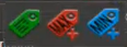
The Tag Settings toolbar provides tools for creating text labels on the model.
For details, see 17. Tags.
2.4.15. Measures#

The Measures Setting tool enables measurements on the model mesh.
For details, see 18. Measures.
2.4.16. Card Manager#

The Card Manager is a visual tool that lets you interact directly with the cards that make up input files (.bdf, .dat, .inc, etc.) for the Nastran and OptiStruct solvers. You can view, filter, edit, and export cards; all edits are validated against the official Nastran and OptiStruct documentation.
For details, see 19. Card Manager.
2.4.17. XY Chart#

The XY Chart button opens a tab containing the chart generation tool. This functionality is independent of the current model visualization. The usage flow is as follows:
Select elements or nodes in the model.
Choose the result to be plotted.
The tool then generates an XY chart based on the selected data, enabling graphical analysis of results for the chosen entities.
For details, see 24. XY_Chart.
2.5. Scripting/Output#
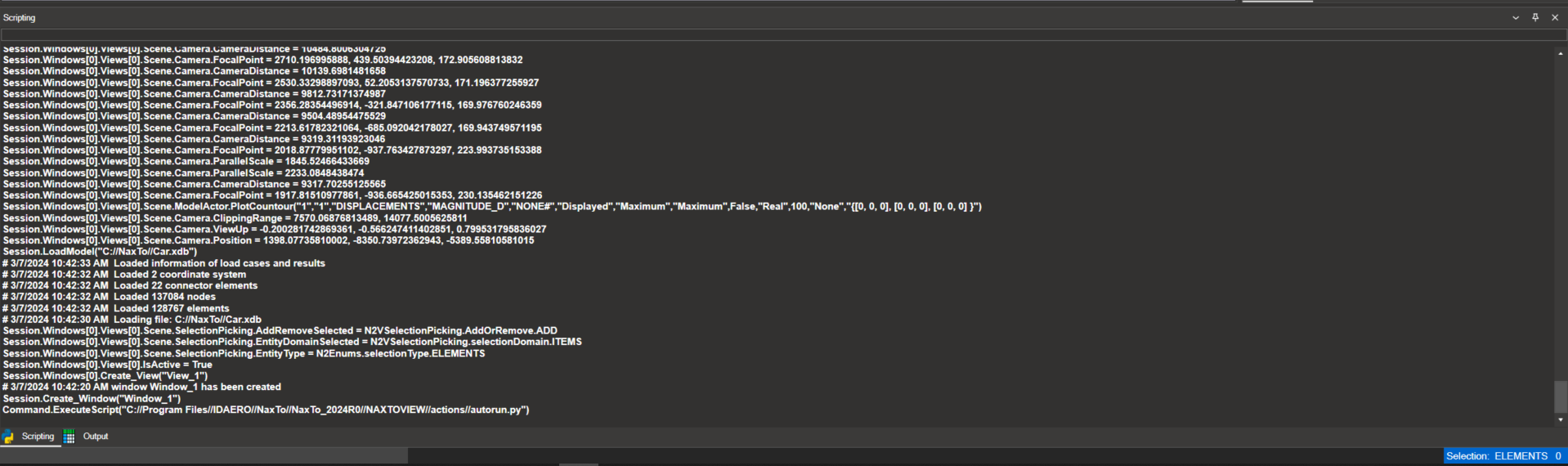
2.5.1. Scripting#
The Scripting tool provides an embedded Python console for executing commands and scripts to control NaxToView.
For details, see 20. Scripting.
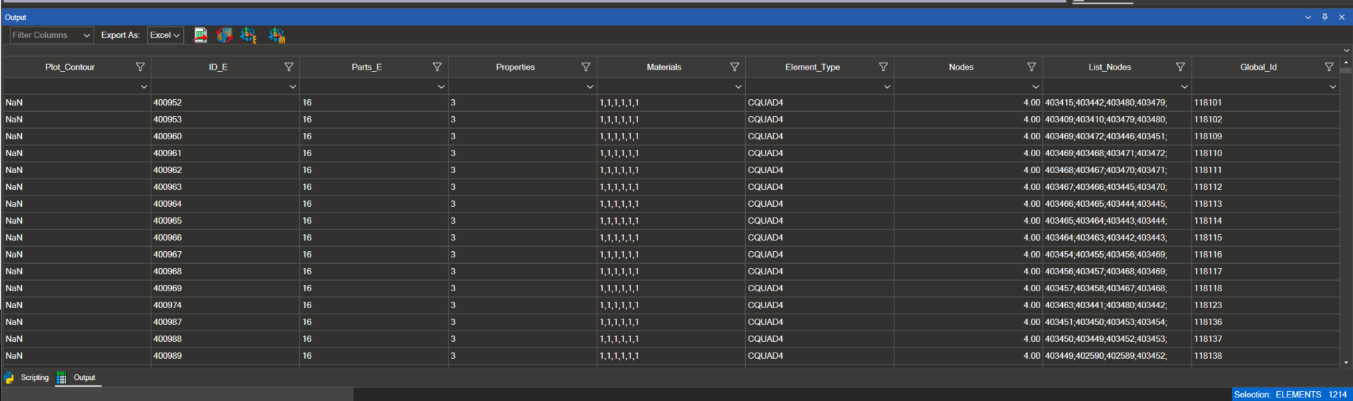
2.5.2. Output#
Displays information for selected elements, nodes, and coordinate systems.
For details, see 10. Output Window.
2.6. Selection Info#
Displays the count of selected elements, nodes, and coordinate systems.
