15. Free Bodies#
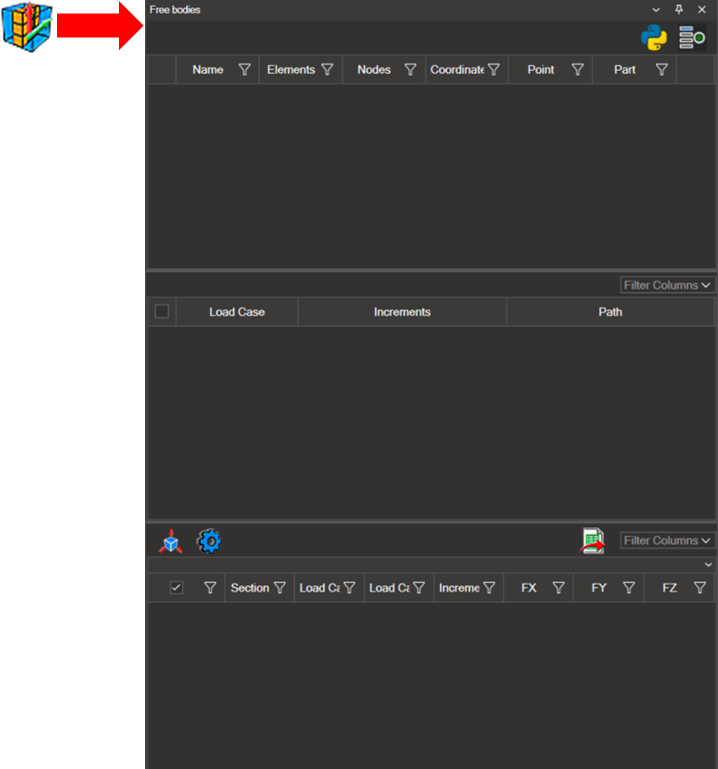
The Free Bodies tool allows you to define sections within the model structure in order to evaluate the forces and moments acting through them.
Note
This functionality is only available in models that include GP Forces.
15.1. Configure the Free Bodies Sections#
To create a new section, click the add icon (
 ) in the upper right corner. Add as many sections as required for the analysis.
To delete a section, click the delete icon (
 ) on the left side of the corresponding row.
Section names can be modified by double-clicking the first column.
Each section must be configured by defining elements, nodes, a coordinate system, an origin point, and a part, as described in the subsections below.
Elements#
Select the elements directly in the model and click the plus icon to add them to the section.

Show/Hide Section Elements#
Clicking the eye icon (
 ) toggles the visibility of the elements associated with the section. Displaying only the section elements makes it easier to review the selection and to identify the related nodes.
Nodes#
Select the nodes in the model and click the plus icon to add them to the section.

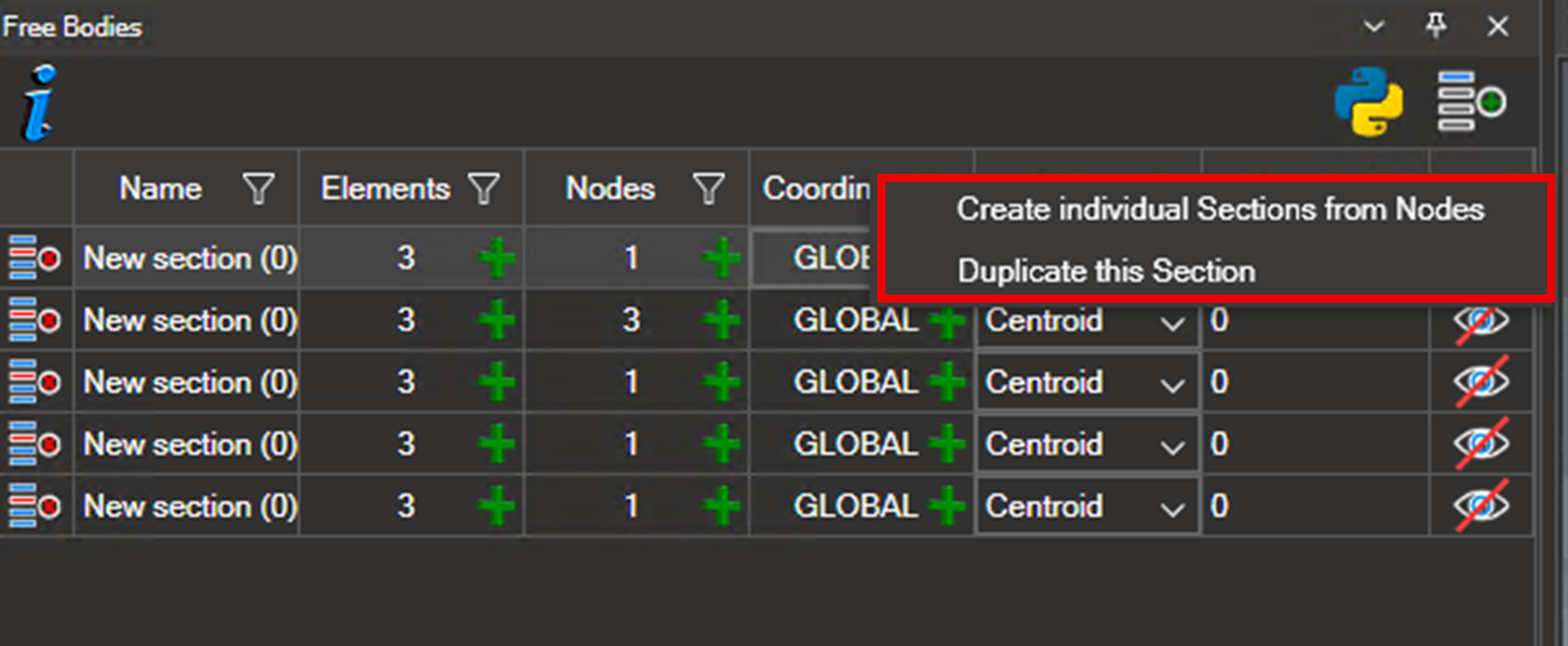
When multiple nodes are selected simultaneously, NaxToView can automatically generate an individual Free Body for each node. To do so:
Click the node count indicator.
Right-click and select Create individual section from nodes.
Coordinate System#
The coordinate system can be defined using one of the following options:
Use the global coordinate system (default).
Select an existing coordinate system from the model.
Create a new coordinate system (see 6.2. Creating a New Coordinate System).
The selected system is highlighted in pink. Click the plus icon to assign it to the section.
Origin Point#
The calculation reference point can be defined using one of the following methods:
Centroid of the selected nodes (default).
Manual input of the X, Y, and Z coordinates.
Select a node in the model — its coordinates are loaded automatically via the plus icon.

Part#
All elements and nodes assigned to a section must belong to the same part. Select the corresponding part in the last column.
Note
All elements and nodes in a section must belong to the same part. Mixing parts within a section will produce incorrect results.

Export Sections#
The export icon ( ) generates a
 .log file containing all defined sections.
This file can be saved in any desired location and reused or shared with other users.
15.2. Load Case and Increment Configuration#
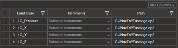
Select the load cases and increments to use for the Free Bodies calculation. For example, selecting Sections A and B with Load Cases 1 and 2 and Increment 1 generates the following combinations:
Section |
Load Case |
Increment |
|---|---|---|
A |
1 |
1 |
A |
2 |
1 |
B |
1 |
1 |
B |
2 |
1 |
15.3. Free Bodies Calculation#
Once the sections, load cases, and increments have been configured, click the Free Bodies icon ( ) to compute the results.
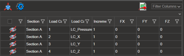
The results table displays:
Section name
Load case
Increment
X, Y, and Z force components
The section name can be edited in the Name field at the top of the results table. Name changes take effect immediately; all other values require recalculation by clicking the Free Bodies icon again.
Additional fields can be enabled via Filter Columns, including:
F Total (sum of force components)
M Total (sum of moment components)
X, Y, and Z coordinates
Directional scalars (nine components)
FX + FY, FY + FZ, FX + FZ
MX + MY, MY + MZ, MX + MZ
The export icon ( ) saves the entire table in Excel format.
Rows and columns (including headers) can be copied using
) saves the entire table in Excel format.
Rows and columns (including headers) can be copied using Ctrl+C.
15.4. Result Visualization#
Click the eye icon ( ) to display Free Bodies in the 3D view.
One section, several sections, or all sections can be activated simultaneously, depending on the analysis requirements.
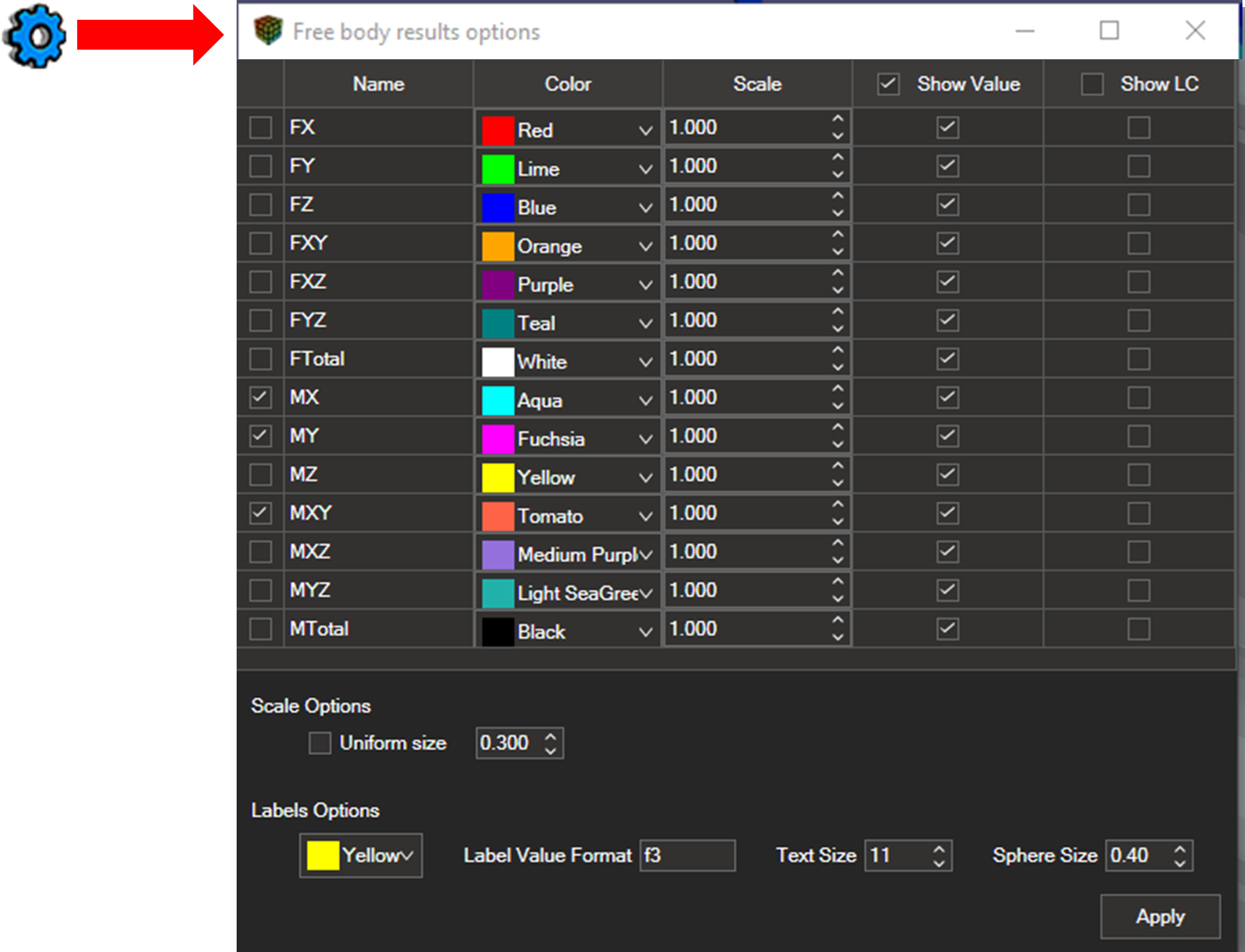
15.5. Free Body Result Options#
The Options gear icon, located to the left of the Free Bodies icon, opens the configuration panel. This panel allows you to adjust:
Force and moment visualization
Color settings
Vector scaling
Label format and color
Size of the spherical indicator associated with each Free Body
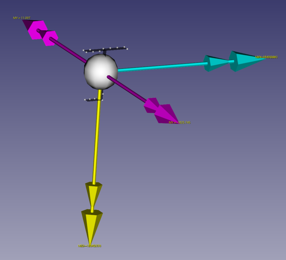
Forces and Moments#
Forces are represented by a single arrow.
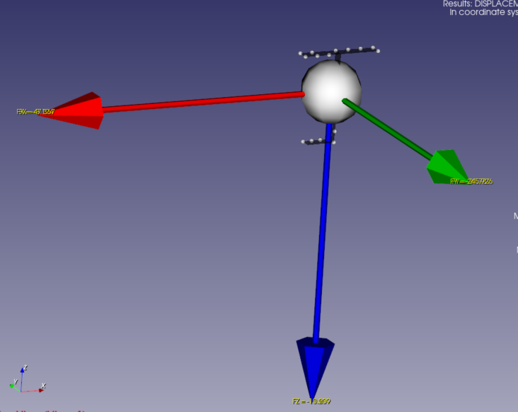
Moments are represented by double arrows.
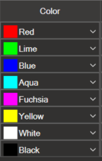
Color#
Allows selecting the colors used for vector representation.
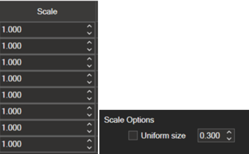
Vector Scale#
Scale Options
Uniform size — all vectors share the same size, defined as a percentage of the model’s smallest dimension (refer to the tooltip for details).
Proportional size (uniform size disabled) — the largest vector adopts the specified length; all other vectors scale accordingly.
Scale Factor
Once the base scale is defined, a multiplier can be applied. For example, a factor of 10 displays the vectors at ten times their scaled size.
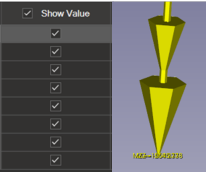
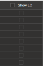
Show Value#
Enables the numerical value displayed at the arrow tip. This setting can be configured individually for each vector.
Show Load Case#
Displays or hides the load case label next to each vector. Label colors can be modified in the lower left area of the panel.
Label Options#
At the bottom left of the panel, you can set the color of the labels.
Value Format#
The following formats are supported:
f3, f6, etc. — decimal notation
e3, e6, etc. — scientific notation
The tooltip provides details about all available formatting rules.
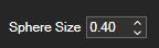
Indicator Size#
The spherical indicator identifying each Free Body can be resized to improve visibility in large or dense models.