10. Output Window#
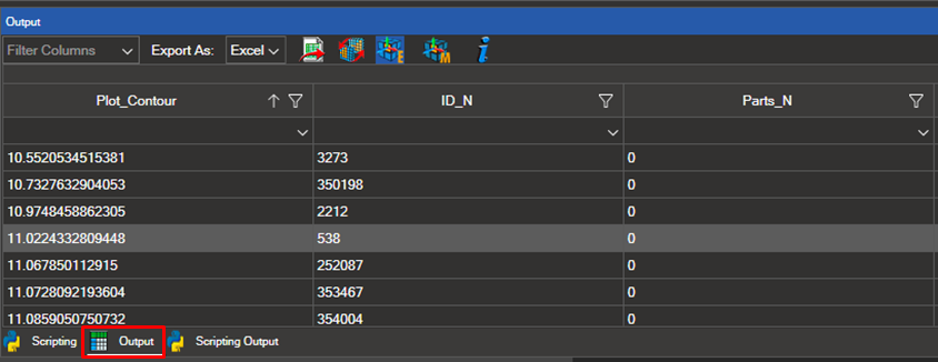
The Output tool displays result data for selected elements, nodes, and coordinate systems in a tabular format. The following sections describe its main features.
10.1. Plot Results and Make a Selection#
Important
A result plot must be active before making a selection. Load a model and apply a contour, vector, or tensor plot first.
Select the elements, nodes, or coordinate systems you wish to analyse. The Output table then displays the results for the active load case and the selected entities.
10.2. Customize Table Columns#
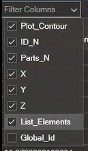
You can show or hide columns in the table. Click Filter Columns in the top left corner of the table to open the column visibility panel.

Check the columns to display and uncheck those to hide. Available columns include plot contour values, element or node IDs, properties, materials, element types, and coordinate systems.
10.3. Filter and Sort Values#
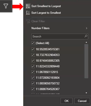
Clicking the filter icon on a column header opens a dropdown menu for filtering by value and sorting in ascending or descending order.
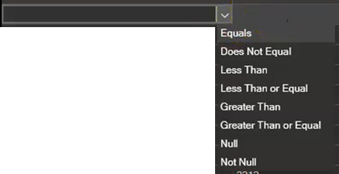
Select a filter operator from the dropdown:
Operator |
Description |
|---|---|
Equals |
Show rows where the value matches exactly |
Does not Equal |
Show rows where the value does not match |
Less than |
Show rows where the value is below the threshold |
Less than or Equal |
Show rows where the value is at or below the threshold |
Greater than |
Show rows where the value is above the threshold |
Greater than or Equal |
Show rows where the value is at or above the threshold |
Null |
Show rows with no value |
Not Null |
Show rows with any value |
Enter the filter value in the input field beside the operator dropdown.
10.4. Export Data#
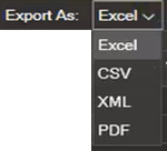
The table data can be exported in Excel, CSV, XML, or PDF format. Select the export format from the dropdown menu and click the corresponding icon.

Clicking this icon updates the selection in the 3D view to match the rows visible in the table.
Note
If any rows are hidden in the table, clicking this icon will also deselect the corresponding elements or nodes in the 3D view.
10.5. Coordinate Axes Visualization#
Use the following icons to display coordinate axes for selected elements directly in the 3D view.
Icon |
Name |
Description |
|---|---|---|

|
Element Coordinates |
Displays the coordinate axes of the selected elements. Click again to hide them. Zoom in on the selected elements to see their axes clearly. |

|
Material Coordinates |
Displays the coordinate axes of the materials assigned to the selected elements. Click again to hide them. |
10.6. Reference Tree#
The Reference Tree is a navigation tool for finite element solver input files (NASTRAN and OptiStruct). For a selected entity, it shows the entities it references (References) and the entities that reference it (Referenced by), together with the fields of the entity’s card. This makes it easy to understand how the cards of an input file depend on each other.
Note
The Reference Tree is only available for models loaded from a NASTRAN or OptiStruct input file (.bdf, .dat, .inc, etc.). It relies on the same card data used by the Card Manager.
10.6.1. Opening the Reference Tree#
In the Output table, right-click the cell of an element, node, property, or material.
Select Open in Reference Tree from the context menu.
The Reference Tree opens for the selected entity, showing its card fields and its dependency lists.
10.6.2. References and Referenced by#
For the entity currently in focus, the Reference Tree displays:
References — the entities that the selected entity points to (the cards it depends on). For example, an element references its property and its nodes.
Referenced by — the entities that point to the selected entity (the cards that depend on it). For example, a property is referenced by the elements that use it.
Alongside these two lists, the panel shows the fields of the selected entity’s card, so you can inspect its values without leaving the Reference Tree.
10.6.4. Opening Entities in Other Tools#
From the References and Referenced by lists you can send any entity to other NaxToView tools:
Open in Card Manager — opens the selected entity directly in the Card Manager, where you can inspect and edit its full card.
Show in Model Tree — for properties and materials, marks the entity in the Model Tree together with its information, so you can locate it within the model hierarchy.
10.7. Viewing Property and Material Information#
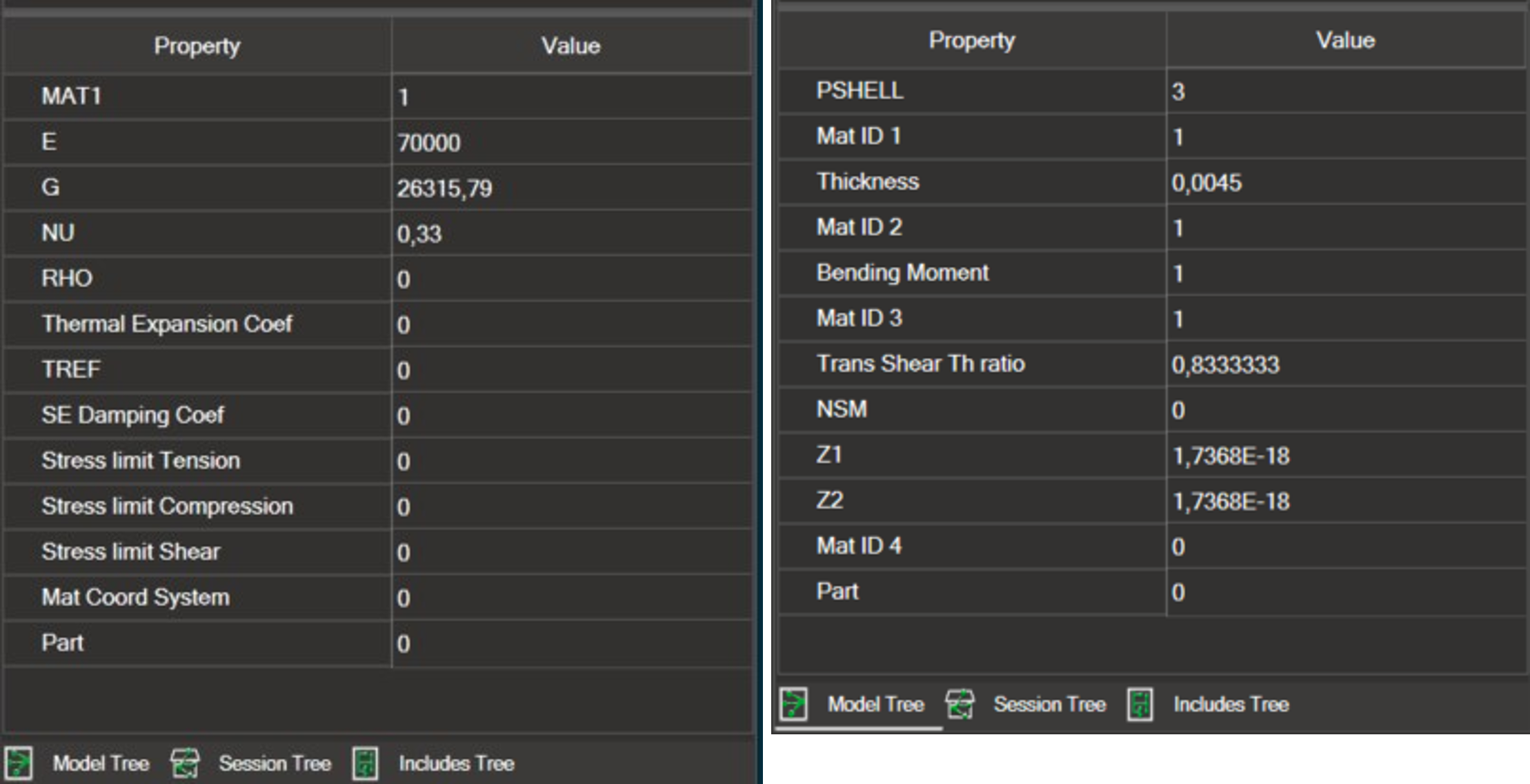
In the output table, you can also double-click a property or material with the left mouse button.
When you do this, the information corresponding to that property or material is displayed in the upper-right panel of the Model Tree.
Note
This option is available for the properties and materials of all loaded models, regardless of their import format.
10.8. Help#

Clicking the Information icon opens the NaxToView online help at this section.